

 English
 русский
 Español
 简体中文
简体中文
Picture a 1.4 m cast-iron housing sitting beside a horizontal machining center. The spindle can remove metal quickly, but the real bottleneck is everything before the first chip: lifting the blank, l...
Read More
How Pneumatic and Manual Vise Systems Redefine Precision Clamping on Vertical Mills
The Clamping Challenge Behind Every Vertical Milling Operation
Every finished part coming off a vertical milling center depends on one variable that rarely gets the attention it deserves: how the raw stock was held during the cut. A spindle can be perfectly calibrated, the tool path flawless, and the coolant flow ideal, yet a part still drifts out of tolerance because the workpiece shifted by a few microns mid-cycle. Workpiece clamping is the silent partner in every dimensional result a shop delivers.
In shops running mixed batch sizes, from single prototypes to production runs of several thousand pieces, the clamping method has to flex without sacrificing repeatability. That is why the conversation around pneumatic vise systems, manual vise systems, and standardized fixture plates has moved from a back-shop detail to a front-line procurement decision.
0.01 mm Typical repeat accuracy target for precision vise jaws
30 sec Average cycle-to-cycle clamping time on pneumatic systems
4x Setup time reduction reported with zero point fixturing
Why Clamping Force Consistency Determines Part Quality
Clamping force is not a single static number. It changes with jaw wear, operator technique, part geometry, and cutting vibration. On a manual system, force is applied by hand torque on a screw mechanism, which means the same operator on two different shifts can produce slightly different clamping pressure. On a pneumatic system, air pressure regulated through a valve delivers the same force cycle after cycle, which is why high-mix, high-volume cells lean toward automated clamping.
Three factors typically dictate how much clamping force a job actually needs:
- Cutting forces generated by the tool, which scale with depth of cut, feed rate, and material hardness
- Part rigidity, since thin-walled or delicate stock can deform under excessive clamping pressure
- Vibration and chatter risk, which increases the demand for consistent, high-magnitude holding force
A vise that clamps too lightly invites part movement and scrap. A vise that clamps too aggressively can distort thin stock before the first pass even begins. The right system finds the narrow band between the two.
Pneumatic Vise Systems: Repeatable Force for High-Volume Vertical Milling
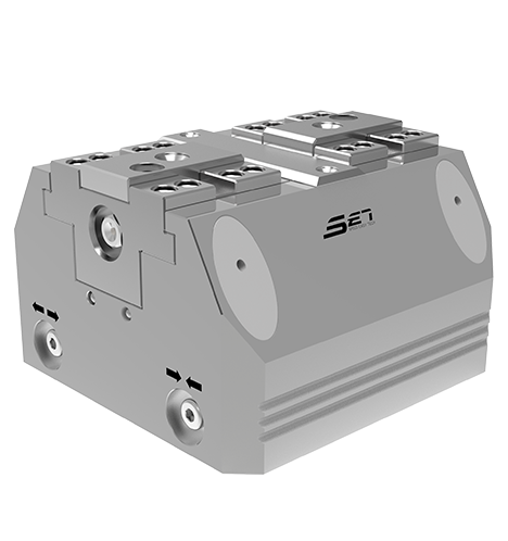
pneumatic vise systems use compressed air routed through a cylinder to actuate the jaw, replacing the manual screw with a controlled, repeatable stroke. Because air pressure can be dialed to a fixed value and held constant, every part in a batch experiences nearly identical clamping conditions. This matters most in cells where a CNC horizontal machining center or a vertical milling center runs unattended through multiple pallet changes.
Common advantages reported in production environments include:
| Attribute | Typical Behavior |
|---|---|
| Clamping consistency | Force variance stays within a narrow, repeatable band across cycles |
| Cycle time | Actuation is triggered automatically, reducing operator dwell time |
| Fatigue impact | Removes repetitive hand-tightening, lowering operator strain over a shift |
| Integration | Can be tied into machine interlocks so the spindle will not start until clamp pressure is confirmed |
The tradeoff is infrastructure. Pneumatic systems require a clean, regulated air supply, additional valving, and periodic seal maintenance. For shops already running air-actuated tombstones or multi-station fixture plates, adding pneumatic vises is a natural extension. For a single manual mill in a low-volume job shop, the air line investment may not pay back quickly.
Manual Vise Systems: Flexible Precision for Prototype and Low-Volume Work
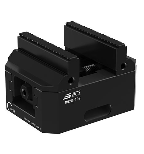
manual vise systems remain the default choice across a large share of job shops, and for good reason. A well-machined manual vise, tightened by an experienced operator, can hold tolerances tight enough for most general milling work without any external air or hydraulic infrastructure. Setup is straightforward: mount the vise, indicate it square to the table, load the part, and tighten.
Manual systems tend to fit best when:
- Batch sizes are small and part geometry changes frequently between jobs
- The shop floor does not already have a regulated compressed air network
- Operators need tactile feedback to judge clamping force on irregular or delicate stock
- Budget constraints favor a lower upfront cost with straightforward maintenance
The limitation is consistency across operators and shifts. Torque applied by hand naturally varies, and on long-running jobs this variance can show up as a slow drift in part dimensions. Many shops address this by pairing manual vises with torque-limiting handles or by documenting a standard tightening procedure in the work instruction.
Pneumatic vs Manual: A Side-by-Side Comparison
| Criteria | Pneumatic Vise Systems | Manual Vise Systems |
|---|---|---|
| Force repeatability | High, regulator-controlled | Moderate, operator-dependent |
| Upfront investment | Higher, requires air infrastructure | Lower, minimal setup |
| Best fit | High-volume, unattended cycles | Prototype and mixed low-volume work |
| Maintenance | Seals, valves, air quality checks | Screw lubrication, jaw wear inspection |
| Automation readiness | Compatible with interlocks and pallet changers | Requires manual intervention each cycle |
Repeatability Cycle Time Operator Fatigue Infrastructure Cost
Zero Point Locator Base Plate: Standardizing Setup Across Machines
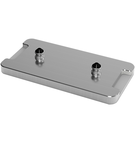
A zero point locator base plate solves a different problem than the vise itself: repeatable location. Instead of re-indicating a fixture every time it moves between machines, a zero point base plate lets an operator drop a pallet or vise onto a set of mechanical locators that snap the fixture back into the same X, Y, and Z reference every time, typically within a few microns.
This becomes especially valuable in shops running a mix of a universal machining center, a dedicated vertical milling center, and a CNC machine gantry for larger parts. A fixture qualified once on one machine can be relocated to another without a full re-indication cycle, which shortens changeover time considerably.
Typical benefits observed in multi-machine cells:
- Fixture qualification is performed once, then reused across multiple machine tools
- Operators spend less time indicating and more time cutting
- Pallet-based work can be staged offline while the machine continues running the previous job
- Repeatability across machines reduces first-article rejection rates
Integrating Clamping Systems Into a Machining Workflow
The diagram below outlines a typical sequence from raw stock to finished part when pneumatic clamping and a zero point base plate are combined on a vertical milling center.
Because the zero point plate removes the indication step and the pneumatic vise removes the manual tightening step, the total non-cutting time between jobs drops significantly, which is one reason many shops standardize on this pairing for repeat production work.
Selecting the Right System for a Universal Machining Center
There is no single correct answer across every shop floor. The right combination depends on part mix, volume, and existing infrastructure. A few practical questions help narrow the decision:
- Does the shop already have regulated compressed air routed to the machine, or would new lines need to be installed
- How often does the fixture need to move between a vertical mill and a horizontal or gantry machine
- Is the current bottleneck cutting time, or is it setup and changeover time
- Do operators need tactile control for delicate or irregular parts, or is force consistency the priority
Many shops land on a hybrid approach: manual vise systems for prototyping and one-off work, pneumatic vise systems for repeat production, and a zero point locator base plate underneath both so the same fixture base can move between machines without re-qualification.
Maintenance and Longevity of Precision Milling Fixtures
Regardless of which clamping method a shop chooses, fixture longevity depends on a consistent maintenance routine. Jaw surfaces wear from repeated contact with raw stock, locating pins accumulate chips and debris, and seals on pneumatic actuators degrade with cycle count and air quality.
| Component | Recommended Check Interval | Failure Symptom |
|---|---|---|
| Vise jaw surface | Weekly visual inspection | Loss of grip, part slippage |
| Pneumatic seals | Every 3 to 6 months | Slow actuation, air leakage |
| Locating pins on zero point plate | Daily wipe-down | Repeatability drift between setups |
| Screw mechanism on manual vise | Monthly lubrication | Uneven or inconsistent clamping force |
Tracking these intervals in a simple maintenance log, rather than relying on memory, is one of the more consistent ways shops keep repeatability stable across months of production.
Frequently Asked Questions
Q1: What is the main difference between pneumatic and manual vise systems?
Pneumatic systems use regulated air pressure to actuate the jaw, giving consistent clamping force across every cycle, while manual systems rely on hand torque, which offers tactile control but more variability between operators.
Q2: Do I need a zero point locator base plate if I only run one machine?
It can still help within a single machine by allowing fixtures to be qualified offline and swapped in quickly, but the benefit becomes larger when fixtures move between multiple machines such as a vertical milling center and a CNC machine gantry.
Q3: Can pneumatic vise systems damage delicate or thin-walled parts?
They can if pressure is not properly regulated for the part, which is why most pneumatic systems allow the operator to set and lock a maximum pressure appropriate to the specific workpiece.
Q4: How much setup time can a zero point base plate actually save?
Shops running repeat jobs commonly report setup time reductions of several times over traditional indicating methods, since the fixture returns to the same reference position without manual alignment.
Q5: Is a manual vise system enough for tight tolerance work?
Yes, in many cases, provided the vise is well maintained, squared correctly, and tightened with a consistent, documented procedure so that force does not vary significantly between parts or shifts.
latest news

- Large Scale CNC Machining: How Workholding and Zero-Point Systems Maximize Output
- Air Gripper Selection Guide: Types, Grip Force, and Automation Integration
- CNC Pallet System Guide: How Zero-Point Pallet Quick Change Cuts Setup Time
- Pneumatic Workholding Solutions: How to Cut Your CNC Setup Time and Errors
Latest news
-
Air Gripper Selection Guide: Types, Grip Force, and Automation IntegrationA robot cell that runs five different part numbers in one shift is no longer unusual. The air gripper at the end of the arm picks and places, but when the product changes, the gripper often has to be...Read More
-
CNC Pallet System Guide: How Zero-Point Pallet Quick Change Cuts Setup TimeImagine a vertical machining center with the spindle stopped while the operator swaps a vise, indicates a fixture, and touches off three new tools. Fifteen minutes per changeover seems small until it...Read More
-
Pneumatic Workholding Solutions: How to Cut Your CNC Setup Time and ErrorsWorkholding is often the hidden time thief in a machining shop. A part that takes three minutes to clamp can turn a 30-second cycle into a 3-minute event, and across a shift that drains every hour of...Read More
-
Machine Tending Tools: How Quick-Change Grippers and Zero-Point Systems Cut CNC DowntimeA production manager watches the clock. The spindle stops, the operator walks over, waits for the table to unclamp, swaps a fixture, re-clamps, and starts the next part. That scene repeats several ti...Read More
-
Machine Tending Fixtures: Key Factors Behind a Stable CNC Machining CellThe night shift operator calls maintenance before the robot has run for an hour. The arm comes down to the same teach point every cycle, but the part is 0.03 mm off in the fixture. Within minutes the...Read More
Contact Details
- Address: 1-4 Floors, 17#03, Building 17, No. 269, Xinfeng Road, Xukou Town, Wuzhong District, Suzhou City
- Fax: +86-18112607008
- Tel: 18112607008
- Email: [email protected]
Mobile terminal
Copyright © SET Industrial | Zero-Point Positioning & CNC Workholding ALL RIGHTS RESERVED.