English
 русский
 Español
 简体中文
简体中文
Five-axis machining has redefined what is geometrically possible on a single setup. Yet the fixture holding your workpiece is just as critical as the machine's kinematics. Without the right workholdi...
Read More
Optimizing 5-Axis Machining: Integrating Dovetail Fixtures and Zero-Point Pallet Systems
Five-axis machining has redefined what is geometrically possible on a single setup. Yet the fixture holding your workpiece is just as critical as the machine's kinematics. Without the right workholding strategy, even a state-of-the-art five-axis center will produce inconsistent parts, require costly re-chucking, and consume spindle time on air cuts rather than metal removal. This article examines two complementary technologies — dovetail fixtures and zero-point pallet systems — and explains how integrating them unlocks the full potential of five-axis production.
Why Conventional Vises Fail in Five-Axis Environments
Standard jaw vises were designed for three-axis milling where spindle approaches are largely axial or lateral. In five-axis work, when a table tilts to 45 degrees or a trunnion swings the part beneath the spindle, conventional vise bodies intrude into the tool path envelope. Machinists must then use extended-reach tooling — and every additional millimeter of overhang multiplies deflection, vibration, and surface error. Studies of five-axis cell efficiency consistently identify toolholder interference with fixtures as one of the top three causes of scrapped programs and re-setups.
Reducing vise height to gain clearance typically means shallower jaw engagement, lower clamping force, and workpiece lift during heavy axial cuts. This trade-off disappears when you shift to a clamping systems philosophy built around the geometry of the part rather than the geometry of a generic jaw.
Key Insight
Low-profile form-fit workholding is not a compromise — it is a geometric solution. By embedding the clamping interface inside the part stock, you recover full five-axis clearance without sacrificing grip force.
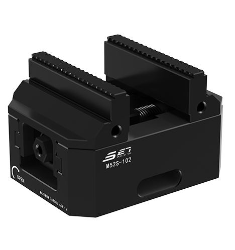
Dovetail Fixtures: Geometry as Clamping Force
A dovetail fixture works by cutting a trapezoidal groove directly into raw stock before it enters the machine. That prepared blank locks onto a matching male dovetail on the fixture body. Clamping force has two components: a downward seating force pulling the part onto the datum, and lateral containment from the angled walls that resists pull-out under cutting loads.
The Dovetail Angle: Balancing Pull-Out Resistance and Release
Shallower angles — typically 45 to 55 degrees from vertical — provide higher pull-out resistance. Steeper angles ease part release and allow faster loading cycles. Most production dovetail fixtures settle between 45 and 60 degrees based on part weight, material, and cutting strategy.
Raw Material Preparation
The dovetail groove is milled into one face of the raw billet before the part program begins — usually on a simple three-axis mill, keeping the expensive five-axis machine free for value-added cutting. Groove depth typically ranges from 3 to 8 mm depending on material hardness and part mass.
45°–60°
Typical dovetail included angle range
3–8 mm
Standard groove depth for most materials
<0.01 mm
Repeatable positioning with precision seating
Low-Profile Clamping: Maximizing Five-Axis Clearance
Low-profile clamping system design keeps all workholding hardware below the parting plane of the finished part — the imaginary boundary above which toolpaths operate without interference. When every element sits below this plane, the full hemisphere of five-axis angular motion is available to the programmer.
Comparing Workholding Profile Heights
| Workholding Type | Height Above Table (mm) | Angular Clearance | Suited for 5-Axis |
|---|---|---|---|
| Standard jaw vise | 120–180 | Below 30° tilt | No |
| Step jaw / soft jaw vise | 80–130 | Up to 40° tilt | Partial |
| Dovetail fixture (standard) | 40–70 | Up to 55° tilt | Yes |
| Dovetail + zero-point pallet | 30–60 | Up to 90° and beyond | Yes (optimized) |
Because the grip interface is recessed into the stock, there are no external straps or jaw extensions protruding above the datum. Typical dovetail fixture body heights run from 40 to 70 mm — roughly half the height of equivalent conventional vise setups.
Form-Fit Clamping in High-Precision Machining
Form-fit clamping describes workholding that conforms intimately to the part's own shape. The dovetail's male and female profiles are a conjugate pair; contact area along both angled faces distributes load evenly — contrasting with point- or line-contact clamping, where high local stress can deform thin-walled features.
- Even stress distribution prevents micro-deflection that corrupts surface finish and dimensional accuracy.
- Self-locating behavior draws the part into the same datum position every cycle, eliminating extra probing on re-chucked blanks.
- Repeatable clamping force via torque-controlled screws or hydraulic wedges enables defined preload, reproducible every cycle.
- Minimal part marking compared to serrated jaws or toe clamps near finished surfaces.
Material Compatibility
Dovetail clamping works across almost all engineering materials. Aluminum alloys are most common due to ease of groove milling. Titanium and nickel superalloys require attention to groove surface finish to avoid stress concentration. Steels above 40 HRC may need the groove milled before heat treatment. Plastics and composites use the same geometry with reduced clamping torque.
Zero-Point Integration: Building a Rapid-Change Pallet System
A zero-point system uses precision receiver modules on the machine table. Each pallet carries matching pull studs; pneumatic or hydraulic actuation locks them with 15,000 to 35,000 N per module, locating the pallet within 0.002 to 0.005 mm repeatably.
Pallet Multiplexing
Most five-axis trunnion tables have enough footprint for two to four zero-point modules. Mounting multiple dovetail fixtures on one pallet — tombstone or multi-face fixturing — multiplies parts cut per cycle. In one documented aerospace bracket cell, shifting from single-part to four-part dovetail arrays on one pallet reduced cost-per-part by 34 percent within the same spindle hours.
Fixture Design Parameters and Key Specifications
| Parameter | Typical Value / Range | Effect of Deviation |
|---|---|---|
| Dovetail angle | 45°–60° | Shallower = more pull-out force; steeper = faster release |
| Groove depth | 3–8 mm | Too shallow = insufficient seating; too deep = part strength loss |
| Land width at groove root | 1–3 mm | Controls stress concentration at groove root |
| Fixture body height | 40–70 mm | Directly determines angular clearance available |
| Dovetail surface finish | Ra 0.8–1.6 um | Rougher increases friction but also notch severity |
For parts above 0.5 kg, always allow at least 4 mm groove depth. Specify a corner radius of 0.3 to 0.5 mm at the groove root to prevent fatigue initiation in high-cycle applications.
Process Planning: Five Steps to Full Integration
- Raw material preparation: Saw or turn blanks to a stock envelope that includes groove allowance and finish stock. A dedicated prep station machines the dovetail groove offline, confirmed by CMM or dedicated gauge.
- Fixture and pallet pre-assembly: Load each dovetail blank into its fixture off-machine (20 to 45 seconds per blank). Seat the fixture on the zero-point pallet and lock the pull stud. Stage the loaded pallet in a queue beside the machine.
- Pallet swap and datum confirmation: Unload the previous pallet; drop the new one into the receiver. A brief two-point touch-probe cycle (under 30 seconds) confirms the part is correctly seated — not re-establishes the coordinate system from scratch.
- Machining and in-process gauging: The five-axis program runs with the datum locked. On-board probe cycles at critical features feed correction offsets back to the program, maintaining Cpk without stopping the cell.
- Post-process and datum removal: The dovetail grip zone is milled to final dimension, removing evidence of the grip engagement, or preserved as a defined reference feature when the drawing requires it.
Economic Case: Measurable Returns on Workholding Investment
The capital outlay for dovetail tooling, fixture hardware, and zero-point receivers is recovered through reductions in non-productive spindle time. Typical improvements in a converted five-axis cell include:
- Setup time: Conventional five-axis vise setup averages 18 to 35 minutes including probing. Zero-point pallet swap with dovetail fixture reduces this to 2 to 5 minutes per family change.
- Scrap reduction: Repositioning errors of 0.02 to 0.08 mm from re-chucking cause measurable scrap on second operations. Dovetail plus zero-point reduces repositioning error to below 0.005 mm, largely eliminating this source.
- Tool life: Rigid, vibration-free workholding enables more aggressive parameters without chatter. Shops consistently report 15 to 25 percent increases in usable tool life when switching to dovetail fixturing on five-axis aluminum work.
- Labor efficiency: Pre-staged pallet queues allow one operator to manage two or three five-axis machines simultaneously, spreading labor cost across greater output volume.
Engineering Note
Always verify fixture pull-out resistance using material-specific friction coefficients and measured groove geometry. Relying on nominal specifications without confirming actual groove depth and surface finish has been a documented root cause of fixture release incidents in production environments.
Frequently Asked Questions
Q1: What is the difference between a dovetail fixture and a dovetail vise?
A dovetail vise is a self-contained unit with both the male dovetail receiver and an adjustable wedge or jaw in one assembly, offering flexibility across different stock sizes. A dovetail fixture is a custom-designed plate engineered for a specific part family, providing higher rigidity and lower profile for dedicated production runs.
Q2: Can dovetail fixtures be used on three-axis machines?
Yes. Many shops introduce dovetail workholding on three-axis centers before upgrading to five-axis. The rigidity, repeatability, and reduced setup time benefits apply equally, and when machines are later converted to five-axis, the same fixtures and pallets carry over with minimal modification.
Q3: How does raw material preparation fit into a lean production cell?
Dovetail groove preparation is performed at an offline prep station running in parallel with the main machining cell. This decouples groove milling cycle time from the five-axis spindle. In high-volume cells, the prep station runs one shift ahead, maintaining a buffer of pre-grooved blanks ready for pallet loading.
Q4: What repeatability can I realistically expect from a zero-point system?
Manufacturers specify 0.002 to 0.005 mm under controlled conditions. In production with normal temperature variation and regular maintenance, 0.005 to 0.008 mm is a realistic expectation — dramatically better than the 0.02 to 0.05 mm from conventional vise setups. For work requiring better than 0.003 mm, a brief in-machine probe cycle confirms the final position after pallet seating.
Q5: Is form-fit clamping suitable for thin-walled or delicate parts?
Dovetail clamping distributes load over a larger area than point clamping, making it better suited to thin-walled parts than jaw vises. The groove must be placed where wall thickness can absorb the preload without distortion. For very thin aerospace shells, supplementary internal mandrels or vacuum chuck faces are often combined with the dovetail interface to prevent spring-back after material stress is relieved during machining.
Q6: How should clamping systems be maintained in high-cycle production?
Zero-point receivers and dovetail fixtures need regular inspection of seating faces for chips, burrs, and wear. Clean and lubricate the receiver bore at each pallet change. Inspect the male dovetail geometry every 200 to 500 cycles for face wear — increased positioning scatter is the first indicator before a catastrophic release becomes possible. Establish a calibration schedule where each fixture is seated and its datum measured against a master reference pallet to catch gradual degradation early.
latest news
- Optimizing 5-Axis Machining: Integrating Dovetail Fixtures and Zero-Point Pallet Systems
- How CNC Tombstones and Zero Point Locator Base Plates Maximize Multi-Axis Productivity
- How Self-Centering Vises and Pneumatic Systems Transform Zero-Point Workholding Precision
- How Zero-Point Clamping Systems Reduce Setup Time by 90% and Enhance CNC Efficiency?
Latest news
-
How CNC Tombstones and Zero Point Locator Base Plates Maximize Multi-Axis ProductivityConventional Vise Setup: 35 min OEE: 43% Tombstone + Zero Point Setup: 90 sec OEE: 86% +210% Throughput In high-mix, high-volume horizontal machining centers (HMC), every non-cutting ...Read More
-
How Self-Centering Vises and Pneumatic Systems Transform Zero-Point Workholding PrecisionPrecision Workholding Engineering Modern multi-axis CNC machining demands workholding that keeps pace with sub-micron tolerances, fast changeovers, and lights-out automation. This guide examines ho...Read More
-
How Zero-Point Clamping Systems Reduce Setup Time by 90% and Enhance CNC Efficiency?Introduction: The Unseen Bottleneck in CNC Machining For decades, CNC machining efficiency has been disproportionately measured by spindle runtime, while workpiece setup time and changeover operatio...Read More
-
How Mechanical Zero Point Base Plates Transform CNC Precision and Workholding EfficiencyUnderstanding Mechanical Zero Point Base Plates in Modern Manufacturing The foundation of precision machining lies in the ability to locate, clamp, and position workpieces with absolute consistency. ...Read More
-
Why Zero Point Positioning Systems Are Essential for Modern CNC ManufacturingUnderstanding Zero Point Positioning Systems In modern manufacturing environments, precision and efficiency are not merely desirable—they are prerequisites for competitive success. The zero point pos...Read More
If you are interested in our products, please consult us
Contact Details
- Address: 1-4 Floors, 17#03, Building 17, No. 269, Xinfeng Road, Xukou Town, Wuzhong District, Suzhou City
- Fax: +86-18112607008
- Tel: 18051849209
- Email: [email protected]
Products
Quick Link
News Center
Mobile terminal
Copyright © Suzhou SET Industrial Equipment System Co.,Ltd. ALL RIGHTS RESERVED.