

 English
 русский
 Español
 简体中文
简体中文
Workholding is often the hidden time thief in a machining shop. A part that takes three minutes to clamp can turn a 30-second cycle into a 3-minute event, and across a shift that drains every hour of...
Read More
How Zero-Point Systems Improve Workpiece Stability in 5-Axis CNC Machining
Why Workpiece Stability Breaks Down When 5-Axis Jobs Get Complex
A 5-axis machining center earns its value by cutting five faces of a part without a single manual re-clamp. That promise collapses the moment a fixture lets the workpiece shift by even a few microns mid-cycle. Tool paths that were programmed against a fixed datum suddenly cut against a moving one, and the part drifts out of tolerance long before an operator notices anything wrong on the display.
Shops that run continuous 4th and 5th axis toolpaths report that the majority of scrapped parts trace back to fixturing, not to the cutter or the program. Repeated bolt-down clamping, T-slot tables, and vise stacks all introduce their own small errors: uneven clamping force, thermal drift from long cycle times, and micro-movement during rapid trunnion rotation. Each of these compounds across a five-face program in a way that a 3-axis job never experiences.
Zero-Point Systems were developed specifically to remove that variable. Instead of re-establishing a datum every time a part is flipped or swapped, the fixture locks to a fixed mechanical reference that stays constant across every setup, pallet, and machine in a shop. Once that reference is established, the programmer, the operator, and the inspection department are all working from the same physical point, which removes one of the most common sources of disagreement between a CAM program and the part that actually comes off the machine.
What a Zero-Point Positioning System Actually Does
At its core, a zero point clamping module is a mechanical coupling: a baseplate or pallet mounted permanently to the machine table, trunnion, or tombstone, paired with a locator pin fixed to the underside of a workpiece, sub-plate, or fixture. When the pin drops into the module and the clamp engages, the part returns to the exact same X, Y, Z, and rotational position every single time, typically within 0.005 mm of repeatability.
This matters most in 5-axis work because it decouples two problems that are normally tangled together: holding the part rigidly, and locating the part precisely. A conventional vise can hold a part rigidly but relies on the operator to re-zero the datum by touching off. A zero point module holds the part rigidly and guarantees the datum never moves, because the mechanical reference is built into the coupling itself rather than into operator technique.
| Clamping Method | Typical Repeatability | Re-Zero Required | Best Fit |
|---|---|---|---|
| Manual vise | 0.02 to 0.05 mm | Yes, every cycle | Prototype, single-part jobs |
| T-slot bolt-down | 0.03 to 0.08 mm | Yes, every cycle | Large, low-volume parts |
| Zero point module | 0.002 to 0.005 mm | No, one-time setup | High-mix, multi-axis, repeat jobs |
Because the reference point is mechanical rather than procedural, the same pallet can move between a mill, a coordinate measuring machine, and a wire EDM without losing its datum. That single trait is what makes zero point tooling the backbone of most modern lights-out and high-mix 5-axis cells.
How the Octagonal Taper Locator Solves Torsional Load
Round taper locators handle vertical clamping force well but resist rotational torque poorly, since a cylindrical taper has no geometric feature to stop the part from twisting under heavy side-milling loads. This is where the Octagonal Taper Zero Point Locator changes the geometry of the problem.
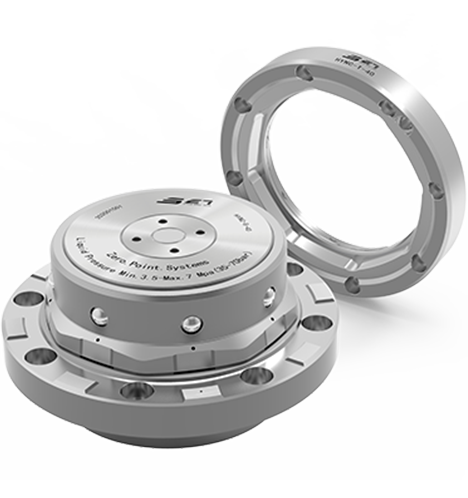
The eight-sided taper profile provides eight discrete flat contact faces instead of one continuous curved surface. During clamping, the locator seats against these flats with a wedging action that resists rotation in both directions, not just vertical pull-down. In a trunnion-mounted 5-axis setup where the table rotates the part through compound angles, that rotational lock prevents the micro-slip that shows up as witness marks or dimensional drift on the finished faces.
- Eight-face contact geometry resists torsional load during heavy side-milling passes
- Self-centering taper angle compensates for minor chip or debris interference
- Hardened and ground contact surfaces maintain repeatability across tens of thousands of clamp cycles
- Compatible with both manual and pneumatic or hydraulic clamping modules
Field data from shops running heavy aerospace-bracket style parts shows torsional deflection under an octagonal taper locator staying below 3 microns even at cutting forces that would visibly rock a round-taper equivalent. For 5-axis programs where the spindle approaches the part from a dozen different vector angles in one cycle, that torsional rigidity is often the difference between a part that holds tolerance and one that does not.
Integrating a Zero Point Positioning System With Trunnion Fixtures
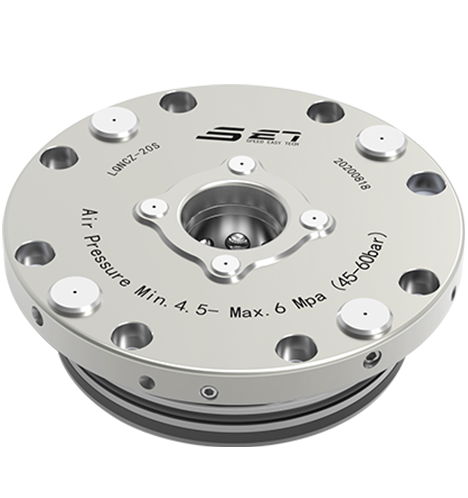
A trunnion table rotates and tilts the workpiece so the spindle can approach features from nearly any angle without a manual re-fixture. That freedom is only useful if the part stays perfectly located through every rotation, which is exactly the job of a Zero Point Positioning System built on a short-cone ball-lock design.
The short-cone geometry keeps the coupling height low, which matters directly on a trunnion because every millimeter of added height increases the swing radius and the inertial load the rotary axes have to manage during rapid indexing. A ball-lock clamp inside the cone pulls the part down with even, radial force distributed around the full circumference, rather than a single-point pull that can rock a workpiece under dynamic rotation.
Three Practical Benefits on a Trunnion Cell
- Lower stack height reduces cantilever load on the rotary axis motors during high-speed indexing
- Even radial clamping force keeps the part centered through tilt angles up to 120 degrees
- Standardized pallet interfaces let one baseplate accept multiple part families without re-tooling the trunnion
Shops that convert a manual-vise trunnion cell to a zero point interface typically report indexing cycle time dropping by 15 to 25 percent, largely because the rotary axis no longer has to decelerate as cautiously through mid-swing to avoid disturbing a loosely referenced part.
Repeatability by Fixture Type: A Visual Comparison
The chart below compares typical positional repeatability across common fixturing approaches, expressed in microns. Lower values indicate tighter, more consistent part location across repeated cycles.
Vibration Amplitude Across a Machining Cycle
Rigid, well-referenced clamping reduces resonant vibration during aggressive multi-axis cuts. The line chart below traces relative vibration amplitude over a single roughing-to-finishing cycle for a manually clamped part versus a zero point clamped part.
The pattern that shows up consistently across shop-floor measurements is that manually clamped parts trend toward higher and more erratic amplitude as spindle speed and side-load increase through a roughing pass, while a rigidly referenced zero point setup stays in a much narrower band. That narrower band is what allows programmers to push feed rates and stepover values more aggressively without risking chatter marks or premature tool wear, since the fixture is no longer the limiting factor on how hard the cut can be pushed.
Multi-Factor Comparison: Zero Point vs Conventional Fixturing
The radar chart below scores each fixturing approach across five practical criteria on a scale of 1 to 5, where a larger enclosed area represents stronger overall performance for high-mix 5-axis production.
How a Setup Changeover Works With a Zero Point Workflow
The diagram below outlines the sequence of a typical high-mix job changeover once a zero point system is installed on the machine table or trunnion.
Because the datum is guaranteed by the mechanical coupling rather than by an operator's touch-off routine, this changeover typically takes under two minutes, compared with fifteen to thirty minutes for a manual re-indication on a comparable trunnion fixture.
A Working Example From High-Mix Bracket Production
Consider a job shop running structural brackets for industrial equipment, machined from aluminum billet across five faces per part in batches of 40 to 80 pieces. Before converting to zero point tooling, each part required a manual re-indicate between the 3+2 roughing operation and the final trunnion finishing pass, adding roughly twenty minutes of non-cutting time per part and introducing enough positional variance that final-inspection rejection ran near six percent.
After standardizing on octagonal taper locators for the roughing fixture and a short-cone zero point positioning system on the trunnion, the shop eliminated the manual re-indicate entirely. Pallets moved directly from the roughing station to the trunnion with the datum intact, non-cutting time per part dropped to roughly four minutes, and final-inspection rejection fell below one percent over a three-month production run.
The efficiency gain came less from faster cutting and more from removing an error-prone manual step, which is the pattern most high-mix shops see once a common mechanical datum spans multiple stations rather than resetting at each one.
Maintaining Long-Term Accuracy Under Daily Production Load
A zero point module is only as accurate as its contact surfaces stay clean. Chips, coolant residue, and fine grit are the most common cause of gradual accuracy drift in shops that skip a basic maintenance routine, since even a few microns of debris trapped between the locator taper and its mating cone will offset the datum on that cycle.
Most shops that run zero point tooling in continuous production build three habits into their standard operating procedure. First, a quick air-blast or wipe-down of both the locator and the baseplate socket before every clamp cycle, which takes seconds but removes the majority of contamination risk. Second, a scheduled dimensional check, typically weekly or every few thousand cycles, using a test indicator or a dedicated calibration puck to confirm the datum has not drifted. Third, tracking clamp-cycle counts per module so that seals, springs, or hydraulic components inside the clamping mechanism are replaced on a preventive schedule rather than after a failure shows up as scrapped parts.
Common Wear Points to Inspect
- Taper or cone contact surfaces for pitting, galling, or coolant staining
- Clamping mechanism springs or seals for reduced pull-down force over time
- Baseplate mounting bolts for torque retention after repeated vibration cycles
- Locator pins on pallets for wear at the initial engagement chamfer
Shops that skip these checks tend to notice accuracy problems only after a batch of parts fails final inspection, at which point the root cause is harder to isolate than it would have been with a routine weekly check. Building the inspection into an existing preventive maintenance schedule, rather than treating it as a separate task, is the most reliable way to keep a fleet of zero point modules performing at their rated tolerance for years rather than months.
Estimating the Return on Standardizing Zero Point Tooling
The financial case for zero point tooling rarely comes from the module cost itself, which is a modest line item compared with the machine time it protects. It comes from three compounding sources: reduced non-cutting time per part, reduced scrap and rework, and reduced dependence on a single experienced operator to hold tolerance by feel.
Non-cutting time is the easiest to quantify. If a manual re-indicate on a trunnion fixture consumes twenty minutes per part and a zero point changeover consumes two minutes, a batch of sixty parts recovers roughly eighteen hours of spindle time that would otherwise sit idle during setup. At a typical shop rate, that recovered time alone often pays back the tooling investment within a single production run of a mid-volume part family.
Scrap reduction compounds on top of that. A shop moving from a six percent rejection rate to a one percent rejection rate on a sixty-piece batch avoids roughly three scrapped parts per run, each carrying the full cost of material, machine time, and programming that has already been sunk into it before the defect is caught. Across dozens of batches a year, that difference alone frequently exceeds the total cost of converting a cell to a common zero point interface.
The third factor is harder to put a number on but matters just as much in practice: consistency that does not depend on which operator ran the setup. A mechanical datum performs the same whether a senior machinist or a recent hire loads the pallet, which reduces the training time needed before a new operator can run high-mix jobs independently.
Selecting the Right Zero Point Configuration
Not every 5-axis job needs the same locator geometry or clamping force. Matching the module to the part family avoids both under-clamping, which risks part movement, and over-specifying, which adds unnecessary cost and stack height.
| Job Characteristic | Recommended Consideration |
|---|---|
| Heavy side-milling, high torque | Octagonal taper locator for rotational resistance |
| Trunnion-mounted, tilt-heavy programs | Short-cone ball-lock positioning system for low stack height |
| Frequent part-family changeover | Standardized baseplate pattern across all fixtures |
| Thin-wall or delicate parts | Distributed, even clamping force over a single high-force point |
| Multi-machine production, shared pallets | Common module interface across mill, inspection, and EDM stations |
Where a job combines several of these traits, most shops standardize on one locator family across the whole cell rather than mixing geometries, since a single mechanical interface simplifies both tooling inventory and operator training.
It also helps to plan the module layout around the part family rather than around a single job. A pallet pattern sized for the largest expected part in a family, with mounting positions left open for smaller variants, avoids the common mistake of designing tooling around one part and then discovering it does not scale as the mix of work changes over a production year. Reviewing upcoming quotes alongside the existing fixture inventory before committing to a locator geometry tends to prevent costly mid-year retooling.
Frequently Asked Questions
Q1: How much positional accuracy can a zero point system realistically hold over time?
Well-maintained hardened-steel modules typically hold repeatability within 0.005 mm across tens of thousands of clamp cycles, though actual figures depend on clamping force, contamination control, and how consistently the mating surfaces are kept clean.
Q2: Is an octagonal taper locator necessary for every 5-axis job, or only heavy-cutting work?
Lighter finishing operations with minimal side load can often run on standard round taper locators. The octagonal geometry earns its cost primarily on roughing or heavy side-milling passes where torsional load is significant.
Q3: Can a zero point positioning system be retrofitted onto an existing trunnion table?
In most cases yes, provided the trunnion surface has enough flat mounting area and the baseplate pattern is matched to the table's bolt spacing. A brief fit check against the trunnion's swing envelope is recommended before ordering.
Q4: Does adding a zero point module reduce the usable clamping area for larger parts?
The baseplate itself adds some height and footprint, but most short-cone designs are built specifically to minimize that penalty, keeping usable table area close to what a bolt-down fixture would offer.
Q5: How does zero point tooling affect changeover time compared with manual indication?
Typical changeover with a zero point interface runs under two minutes per part, compared with fifteen to thirty minutes for a full manual re-indicate on a comparable trunnion fixture.
latest news

- Pneumatic Workholding Solutions: How to Cut Your CNC Setup Time and Errors
- Machine Tending Tools: How Quick-Change Grippers and Zero-Point Systems Cut CNC Downtime
- Machine Tending Fixtures: Key Factors Behind a Stable CNC Machining Cell
- 5-Axis Workholding: How Zero-Point Systems and Vises Maximize Machining Stability
Latest news
-
Machine Tending Tools: How Quick-Change Grippers and Zero-Point Systems Cut CNC DowntimeA production manager watches the clock. The spindle stops, the operator walks over, waits for the table to unclamp, swaps a fixture, re-clamps, and starts the next part. That scene repeats several ti...Read More
-
Machine Tending Fixtures: Key Factors Behind a Stable CNC Machining CellThe night shift operator calls maintenance before the robot has run for an hour. The arm comes down to the same teach point every cycle, but the part is 0.03 mm off in the fixture. Within minutes the...Read More
-
5-Axis Workholding: How Zero-Point Systems and Vises Maximize Machining StabilityA five-axis machining center is only as good as the workholding that supports it. A fixture that blocks the rotary table or interferes with the cutter path turns a five-axis machine into a three-axis...Read More
-
How Do Locating and Alignment Accessories Define CNC Machining Accuracy?Introduction: The Hidden Cost of Misalignment In CNC machining, the difference between a high-value precision component and a scrap part often comes down to a fraction of a millimeter. While spindles...Read More
-
What Clamping System Delivers the Best Accuracy and Throughput for Your Vertical Machining Centre?Why Clamping Systems Define VMC Performance In vertical machining centres, the clamping system is not a passive accessory—it is the structural link between the machine spindle and the workpiece. A ri...Read More
If you are interested in our products, please consult us
Contact Details
- Address: 1-4 Floors, 17#03, Building 17, No. 269, Xinfeng Road, Xukou Town, Wuzhong District, Suzhou City
- Fax: +86-18112607008
- Tel: 18112607008
- Email: [email protected]
Products
Quick Link
News Center
Mobile terminal
Copyright © SET Industrial | Zero-Point Positioning & CNC Workholding ALL RIGHTS RESERVED.