

 English
 русский
 Español
 简体中文
简体中文
A robot cell that runs five different part numbers in one shift is no longer unusual. The air gripper at the end of the arm picks and places, but when the product changes, the gripper often has to be...
Read More
Air Gripper Selection Guide: Types, Grip Force, and Automation Integration
A robot cell that runs five different part numbers in one shift is no longer unusual. The air gripper at the end of the arm picks and places, but when the product changes, the gripper often has to be swapped manually. That swap costs time. Choosing the right air gripper therefore determines cycle time, changeover effort, and whether the cell can run unattended. This guide explains how air grippers work, which specifications matter, and how a quick-change interface turns a fixed automation cell into a flexible one.
What Is an Air Gripper and How Does It Work?
An air gripper, also called a pneumatic gripper, is an end-of-arm actuator that uses compressed air to open and close jaws. Air pushes a piston; the piston drives a wedge, lever, or slide; and the jaws move toward or away from the workpiece. When air is released, return springs or the opposite air port bring the jaws back.
Most pneumatic grippers support two modes: external gripping, where the jaws close around the part, and internal gripping, where the jaws expand inside a bore. Many are also centric, meaning both jaws move symmetrically around a fixed center line, which keeps the workpiece position stable.
Repeatability is a key reason manufacturers choose air grippers. A well-built unit returns to the same jaw position within ±0.01 to 0.05 mm, which is enough for most pick-and-place, machine tending, and assembly work. Sensor slots allow magnetic or inductive proximity switches to confirm whether the jaws are open, closed, or holding a part.
Air Gripper Types and When to Use Them
The first selection step is the jaw configuration. Each type has a natural area of use:
- Parallel two-jaw grippers keep the jaws parallel through the whole stroke. They suit rectangular parts, internal bores, and any task where a predictable pick point matters.
- Angular two-jaw grippers rotate the jaws around a pivot. They open very wide for a compact body, which helps when a flange or protruding contour has to pass between the jaws.
- Three-jaw grippers move three jaws radially together, so round or hexagonal workpieces are centered automatically.
- Long-stroke grippers provide extra travel for large panels, tubular parts, or reaching over an obstacle.
The table below summarizes the trade-offs:
| Gripper Type | Jaw Motion | Typical Workpieces | Best Application |
|---|---|---|---|
| Parallel two-jaw | Linear | Rectangular parts, flat panels, bores | Pick-and-place, machine tending |
| Angular two-jaw | Pivoting | Flanges, round housings, contoured parts | Assembly, limited-clearance loading |
| Three-jaw | Radial | Cylinders, rods, hexagonal parts | Centering, lathe and gear handling |
| Long-stroke | Linear wide travel | Large panels, tubular profiles | Bulky parts, overhead clearance |
For lathe loading, a three-jaw gripper gives the fastest centering. For picking a casting from a tight nest, an angular gripper opens wider. For general-purpose automation, parallel jaws give the most predictable geometry.
How to Select the Right Air Gripper
Calculate grip force first
The most important specification is grip force, the sum of the forces applied by all jaws. The part must not slip during acceleration, deceleration, or an emergency stop. A practical formula is:
Required grip force = (workpiece mass × (gravity + maximum acceleration) × safety factor) ÷ friction coefficient
For a 2 kg steel part with 10 m/s² acceleration, a friction coefficient of 0.5, and a safety factor of 3, the required grip force is (2 × (9.81 + 10) × 3) ÷ 0.5 ≈ 238 N. With two jaws sharing the load, each must deliver about 119 N. A gripper rated at 100 N per jaw is not enough; 150 N per jaw gives a comfortable margin.
Check stroke, operating pressure, and repeatability
Stroke comes second. The jaws must clear the workpiece and fixture lip, but a longer stroke usually lowers the available force for the same body size. Pressure matters too: most grippers are rated at 4 to 7 bar, and a plant running at 5 bar cannot use a 6 bar rating. Repeatability of ±0.01 to 0.05 mm is typical; choose the tighter end for press-fit or assembly.
Consider the environment and feedback signals
Coolant, cast-iron dust, and oil are normal in a machining cell, so sealed bodies and IP-rated sensors prevent premature failures. Sensor cables need strain relief, especially on a quick-change system, because flexing at the connection causes intermittent signals. For unattended operation, open/close confirmation is not optional.
Gripper Quick Change: Making Air Grippers Flexible
Once the gripper is selected, the next question is mounting. Direct flange mounting works when one robot performs the same task all day, but in mixed-model production, a product change can cost 15 to 30 minutes of manual work: disconnecting air lines, unplugging sensors, removing bolts, re-running tests. A gripper quick-change device shortens this to seconds by separating the robot-side master from the tool-side adapter.
With a quick-change interface, the robot drops one air gripper, picks up another, and verifies the lock through sensors. Size the device by payload and moment, not just gripper weight. A light plastic-part cell works well with a 25 kg class unit, while heavy machining needs 75, 100, or 150 kg units. This is covered further in our article on how quick-change devices drive industrial automation.
Typical quick-change gripper units combine a locking mechanism, air pass-through ports, and electrical signal transfer in one package:
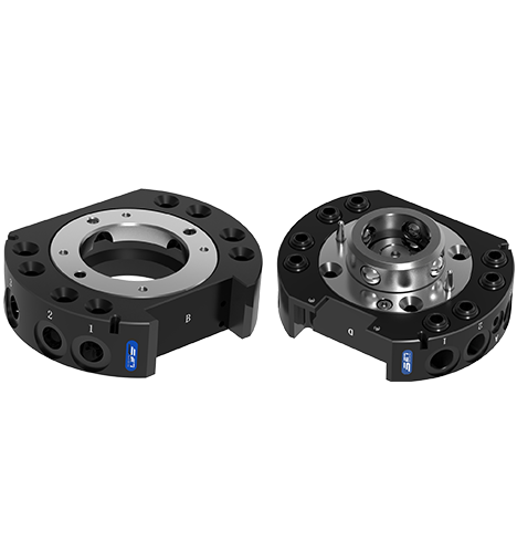 25kg Pneumatic Quick-Change Gripper with Locking ForceThis compact quick-change unit carries 25kg workpieces with a 2300N locking force and ±0.015mm repeatability, making it a reliable base for modular end-of-arm tooling in automated handling and assembly tasks.View Product →
 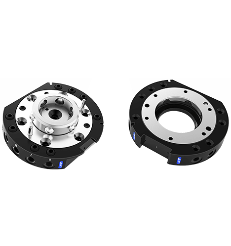 75kg Pneumatic Quick-Change Gripper for Heavy PayloadsWith a 7400N locking force and 75kg carrying capacity, this hardened stainless-steel gripper supports heavier automation applications while maintaining ±0.015mm repeatability and optional power, liquid, and gas modules.View Product →
 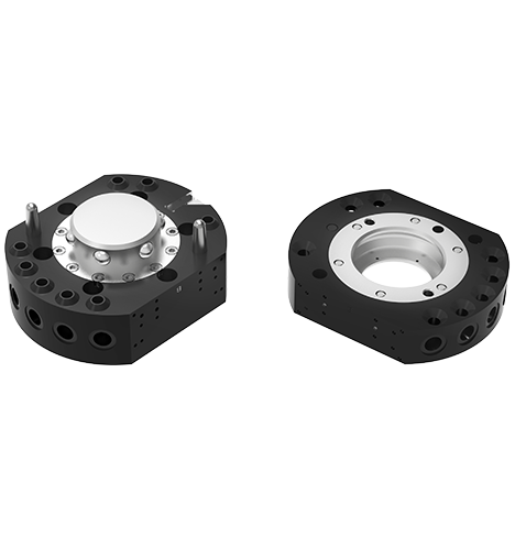 150kg High-Capacity Quick-Change Gripper with 12kN LockDesigned for demanding payloads, this gripper handles 150kg workpieces with a 12000N locking force, ±0.015mm repeatability, and accessory modules for power, liquids, and gases, suited for heavy-duty automated assembly.View Product →
When you add air grippers to a quick-change system, check that the pneumatic ports match the gripper's air consumption and that electrical modules carry sensor signals without crosstalk. The same logic applies to robot-side layouts; see our end-of-arm gripping applications page for examples.
Common Air Gripper Applications
Air grippers appear wherever a robot must handle solid, non-porous workpieces reliably. Common tasks include:
- CNC machine tending: loading blanks and unloading finished parts, often with three-jaw or parallel grippers.
- Pick and place: sorting and transferring parts between conveyors and trays.
- Assembly: inserting pins, seating covers, and pressing small components.
- Packaging: gripping cartons, bottles, or foam inserts at high speed.
- Inspection and testing: moving parts to gauges, cameras, or leak-test stations.
Compared with vacuum cups, mechanical jaws handle oily, wet, or rough surfaces better because no seal is required. A machined steel pad grips through cutting fluid, while a vacuum cup would slide or release.
Maintenance and Common Mistakes
An air gripper is a mechanical component, so it wears. Three practices extend its life:
- Keep the air clean and dry. A filter-regulator-lubricator set prevents water and particles from damaging piston seals. Moisture is the main cause of sticky jaws.
- Lubricate as scheduled. Some grippers have a service port; others need periodic oil. Skipping lubrication shows up as slow opening or closing.
- Protect jaw pads from side loads. A gripper is designed to take force along its jaw axis; pushing sideways during insertion wears the guides quickly.
Common mistakes include oversizing force for soft plastic parts, which deforms them, and undersizing for high-speed robots, which drops parts on emergency stop. Do not rely on a 6 bar rating when your supply runs at 5 bar; size with a safety factor between 2 and 4 times the calculated load.
Frequently Asked Questions
Q1: What air pressure do pneumatic grippers typically need?
Most air grippers are rated for 4 to 7 bar. Grip force scales with pressure, so check the force-stroke diagram and calculate at your actual plant pressure, not the catalog maximum.
Q2: How much grip force do I need for a 3 kg workpiece?
Use F = (m × (g + a) × s) ÷ μ. For m = 3 kg, acceleration = 10 m/s², μ = 0.5, and safety factor = 3, you need about 357 N total, or 179 N per jaw on a two-jaw gripper. Increase the factor if the part is oily or the path is aggressive.
Q3: Can an air gripper hold a part during fast robot movements?
Yes, if the grip force covers acceleration and deceleration. At 15 m/s², a 2 kg part adds roughly 30 N of inertial load to its 19.6 N weight. Apply a safety factor and the installation stays reliable.
Q4: What is the difference between an air gripper and an electric gripper?
An air gripper is faster, simpler, and lower cost for open/close tasks with fixed stroke. An electric gripper adds position control and adjustable force for fragile parts or variable widths. Choose electric when jaw position control is required; otherwise air is the practical option.
Air gripper selection starts with jaw type, continues with grip force calculated against real acceleration and pressure, and finishes with sensors for unattended operation. The quick-change interface then decides how fast the cell switches products. With the right air gripper and a matched quick-change device, one robot station can serve several part families without long changeover stops.
latest news
- Air Gripper Selection Guide: Types, Grip Force, and Automation Integration
- CNC Pallet System Guide: How Zero-Point Pallet Quick Change Cuts Setup Time
- Pneumatic Workholding Solutions: How to Cut Your CNC Setup Time and Errors
- Machine Tending Tools: How Quick-Change Grippers and Zero-Point Systems Cut CNC Downtime
Latest news
-
CNC Pallet System Guide: How Zero-Point Pallet Quick Change Cuts Setup TimeImagine a vertical machining center with the spindle stopped while the operator swaps a vise, indicates a fixture, and touches off three new tools. Fifteen minutes per changeover seems small until it...Read More
-
Pneumatic Workholding Solutions: How to Cut Your CNC Setup Time and ErrorsWorkholding is often the hidden time thief in a machining shop. A part that takes three minutes to clamp can turn a 30-second cycle into a 3-minute event, and across a shift that drains every hour of...Read More
-
Machine Tending Tools: How Quick-Change Grippers and Zero-Point Systems Cut CNC DowntimeA production manager watches the clock. The spindle stops, the operator walks over, waits for the table to unclamp, swaps a fixture, re-clamps, and starts the next part. That scene repeats several ti...Read More
-
Machine Tending Fixtures: Key Factors Behind a Stable CNC Machining CellThe night shift operator calls maintenance before the robot has run for an hour. The arm comes down to the same teach point every cycle, but the part is 0.03 mm off in the fixture. Within minutes the...Read More
-
5-Axis Workholding: How Zero-Point Systems and Vises Maximize Machining StabilityA five-axis machining center is only as good as the workholding that supports it. A fixture that blocks the rotary table or interferes with the cutter path turns a five-axis machine into a three-axis...Read More
Contact Details
- Address: 1-4 Floors, 17#03, Building 17, No. 269, Xinfeng Road, Xukou Town, Wuzhong District, Suzhou City
- Fax: +86-18112607008
- Tel: 18112607008
- Email: [email protected]
Mobile terminal
Copyright © SET Industrial | Zero-Point Positioning & CNC Workholding ALL RIGHTS RESERVED.